Intro
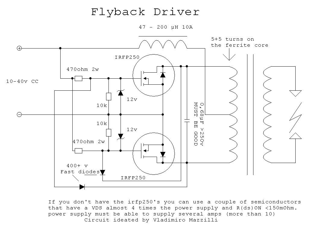
The Mazilli ZVS driver, also known as the Royer driver, is a self resonant, push-pull, free running oscillator that uses a transformer to make a high voltage. This driver is very efficient since the two switching devices are driving a parallel LC tank at its resonant frequency. This means that the switching devices see a high impedance resistive load and are happy with switching it. Happy as in, not going up in flames due to excessive power dissipation be it in the gate or excessive avalanching. For each cycle, the switches have to make up the lost power so if there is no load on the transformer and low capacitor losses, the driver will draw very little power. Only when there is a load or losses in components does the current rise. This is because the driver makes up the lost power by feeding more in via the switches. The switching devices can be either BJTs or MOSFETs. BJTs need a feedback loop to supply current to the transistorÆs bases. The Mazilli driver uses MOSFETs and diodes to turn the MOSFETs on or off depending on the tankÆs voltage.
Where is/was it Used?
The ZVS flyback driver ¢ either using BJTs or MOSFETs ¢ have been used in high voltage devices such as tesla coils, marx generators, ion experiments, and CCFLs. Most of the people in the 4HV community use the Mazilli driver to make flyback transformers ¢ also known as Line Output Transformers (LOPT) ¢ from TVs and computer monitors output more power than they are designed for to draw arcs. One interesting thing is that these drivers are rather difficult to simulate on a computer since in an ideal world, it doesnÆt work at all. ThereÆs nothing to start the oscillations. Due to differences in component values in real life, one switch turns on first and then it will continue oscillating until power is removed.
How I Came Across This and why I Built it
Of the handful of high voltage transformers, I wanted to mess around with the flyback transformer since it was easier to get one than, say, a neon sigh transformer. I was looking for ōnewer flybackö driver designs and came across this one after quite a bit of searching. Most of the others I had seen were simple 555 based drivers and ones similar to the single or double 2N3055 transistor design. These drivers were prone to failure and had high losses in the switching devices. I found most of the information on the Mazilli driver in the 4HV forums and eventually joined to post my working driver to see if and what improvements could be made.
Design and Construction
Before trying to make a high power design, a MOSFET was selected that my local electronics store had rather cheaply. The MOSFET had to, like the sheet says, have a high enough Vds so that it doesnÆt break down and a low enough Ron so that the device doesnÆt heat up much when passing large currents that would be drawn when drawing an arc. While doing research before actually acquiring the parts, someone noted that a low gate capacitance would also help cut down on power loss since less energy will moving to and from the die each cycle. Large gate capacitances also slow down the switching time which would cause the FET to linger in the linear region of operation longer dissipating more power. This is also the reason for not increasing the pull up resistors too high and choosing a FET with fairly fast rise and fall times.
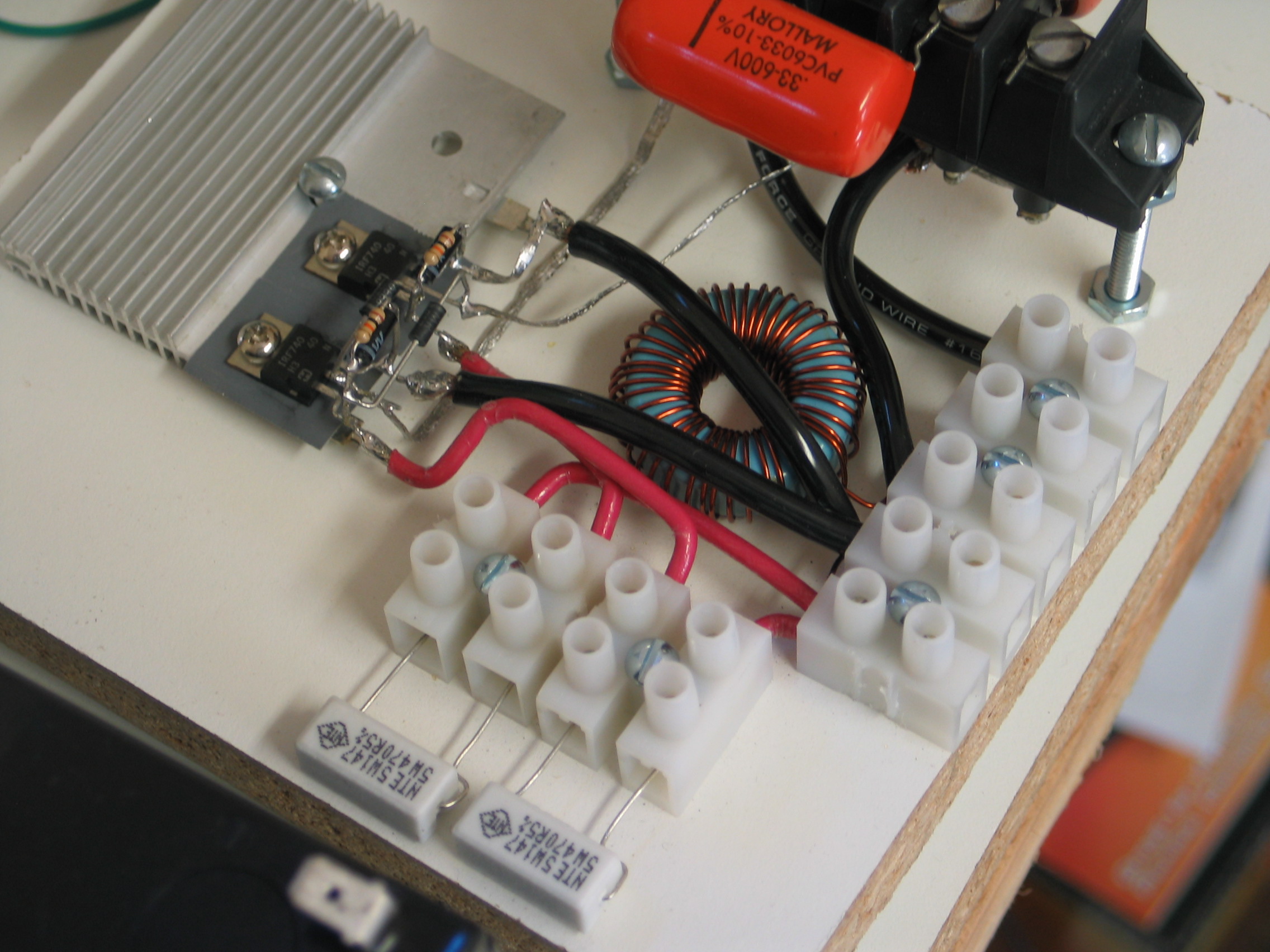
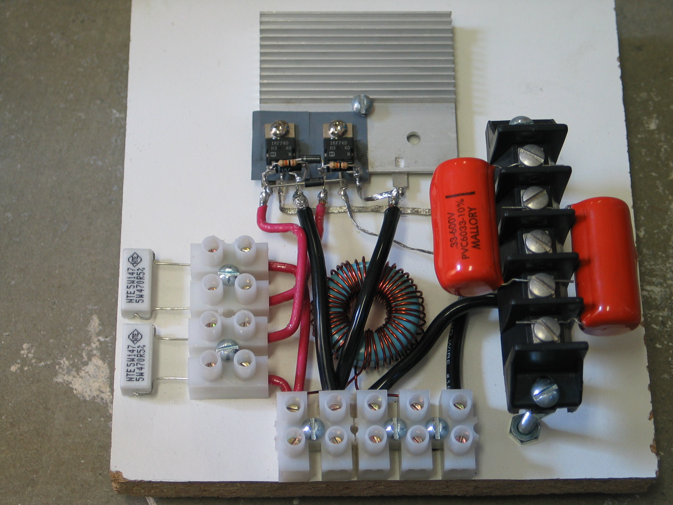
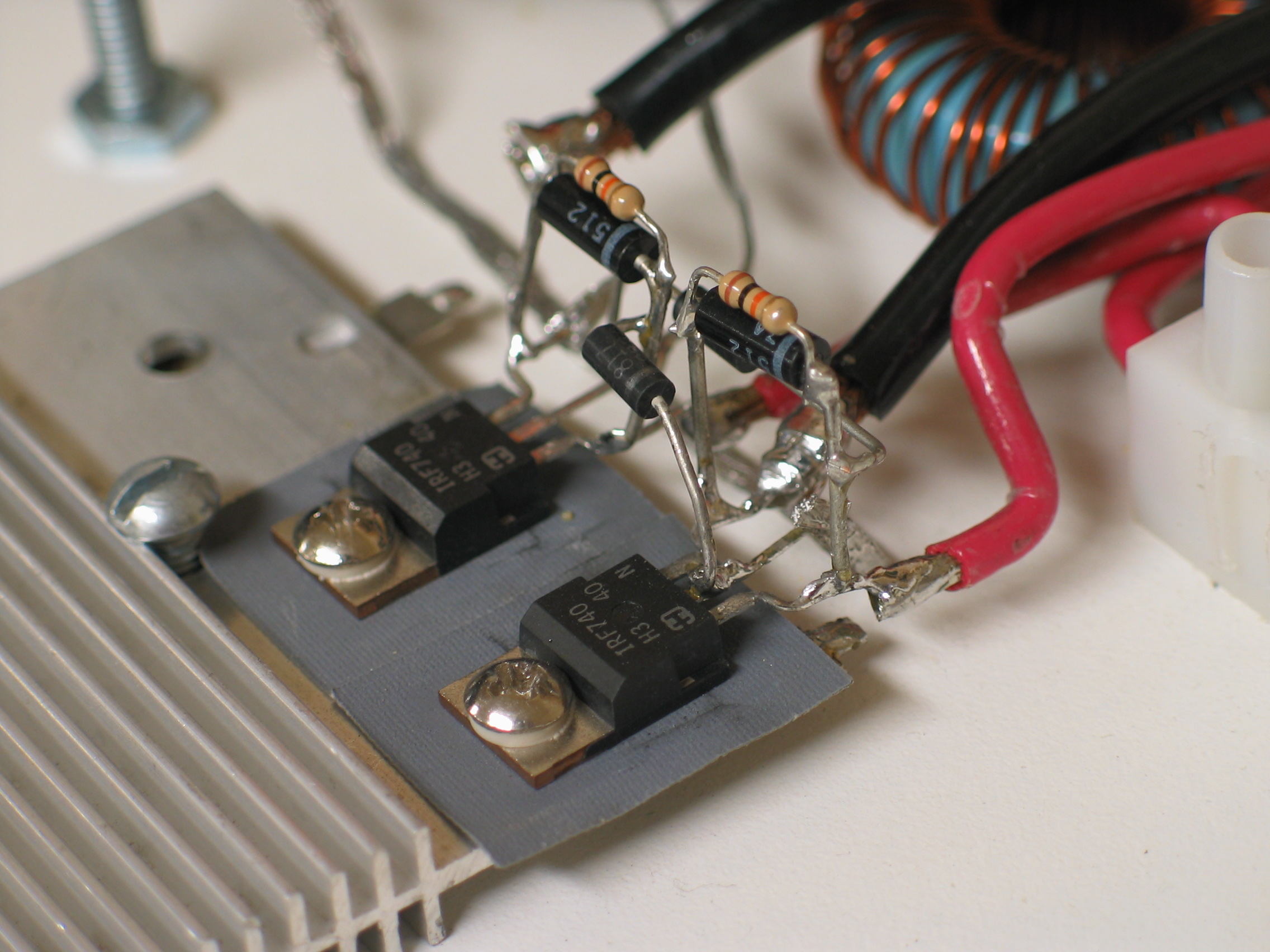
The IRF740 seemed like it should work fine for low enough voltages so that the maximum current isnÆt exceeded. I just had to be careful and monitor the current and keep it below 10A. I couldnÆt use a digital meter since they donÆt like anything besides DC. Also the high frequency component of the current messes with the reading. A 50A analog meter from my local swap meet did quite well.
For the capacitors, I picked the ones my local store had available. Because the single high voltage capacitors didnÆt fall in the range of 1-0.47ĄF, I put two 0.33ĄF 600V capacitors in parallel to get 0.66ĄF. I wasnÆt sure they could handle large circulating currents since they didnÆt seem to be made for LC tanks but after runs, I checked the temperature of the capacitors to make sure they werenÆt heating up too much.
The Mazilli circuit doesnÆt tolerate large series inductances even though the frequency is low I guess. There have been people who have had long wires cause problems in stable oscillation. Either way, the wires are carrying high currents and should be kept short and thick to minimize power losses.
4HV members had recommended using a toroid from an ATX power supply so I took a broken one apart. The core had to be iron powder (normally yellow/white or blue) so it didnÆt saturate and serve its purpose, supply current when the circuit needs it so it can continue oscillating. This is also a reason why the voltage between the drain and source of the MOSFETs is about 3 to 4 times higher than the supply voltage.
For my power supply, I used old-ish 12V 7Ah batteries that were going to be recycled at my local electronics store. They gave them to me for free and said that if they stopped working, I could just bring them back in and take some other ones. Since some of them were low on charge, I built this battery charger so I could try to get as much power from the used batteries as possible. It worked quite well and helped prevent the battery voltage from dropping really far under a high load.
Here is the first finished driver (finished around 2/19/07)
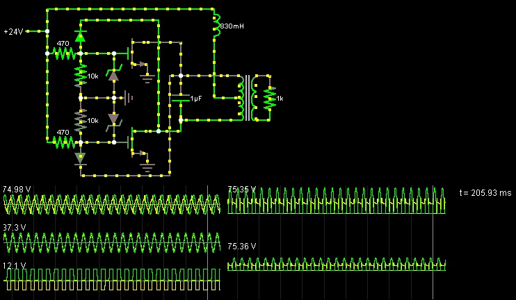
A working simulation by Bj°rn
The IRF740s limited the current I was willing to put into the driver and also, they heated up a fair amount mainly because they have a high Ron. I also hit parasitic oscillations at a fairly low voltage but I didnÆt know what they were except the driver sometimes didnÆt work and only put out a spark instead of being able to draw arcs. Parasitic oscillations are when the stray capacitances and inductances somewhere resonate and throw off the operation of the circuit. This occurs at the higher voltages because the devices can switch at that speed with a higher voltage gate drive. When the driver hits parasitic oscillations, the output from the flyback drops to nothing and may kill one of the MOSFETs due to die heating. This can be avoided somewhat by using separate supplies for the gate and flyback.
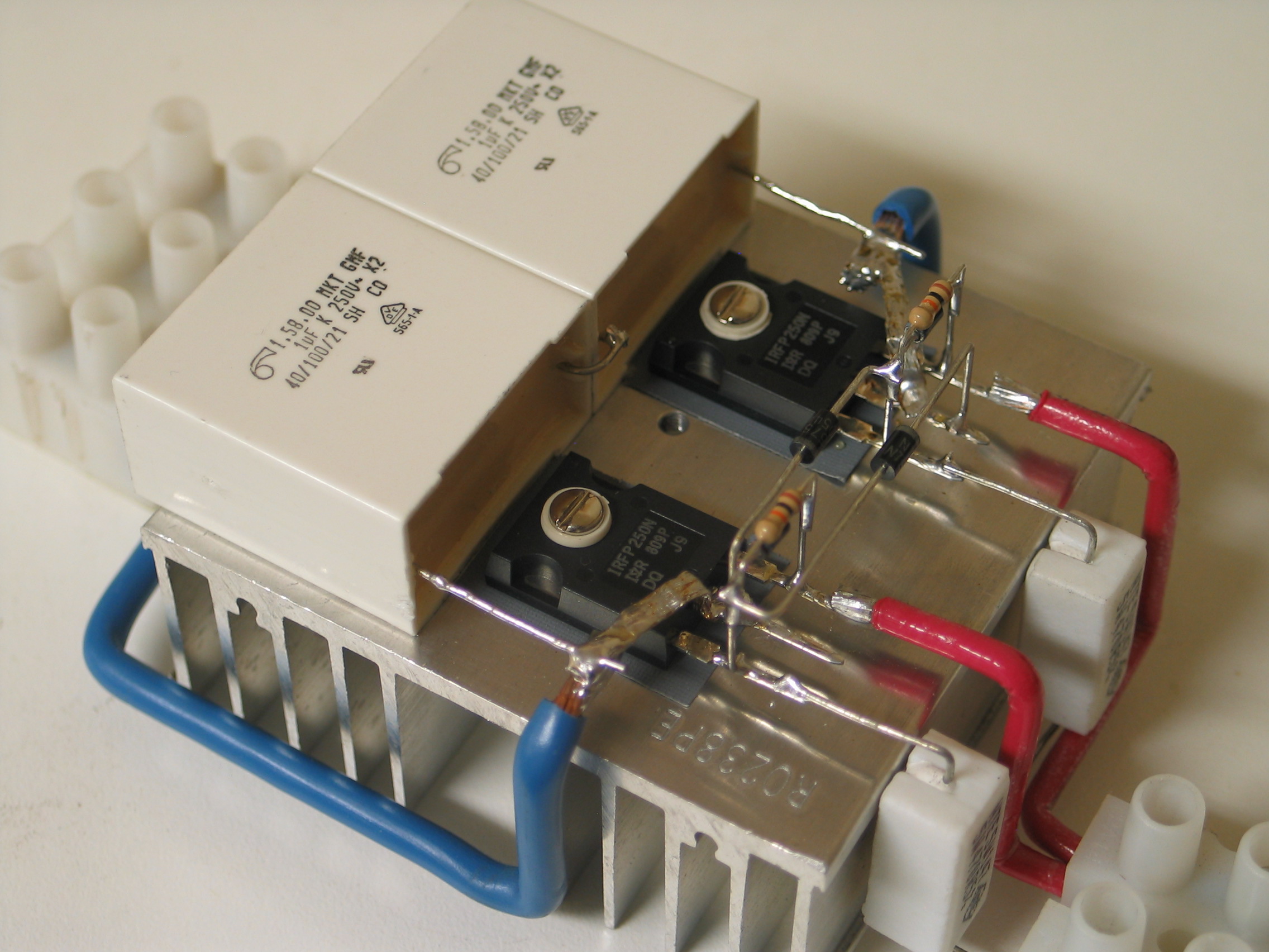
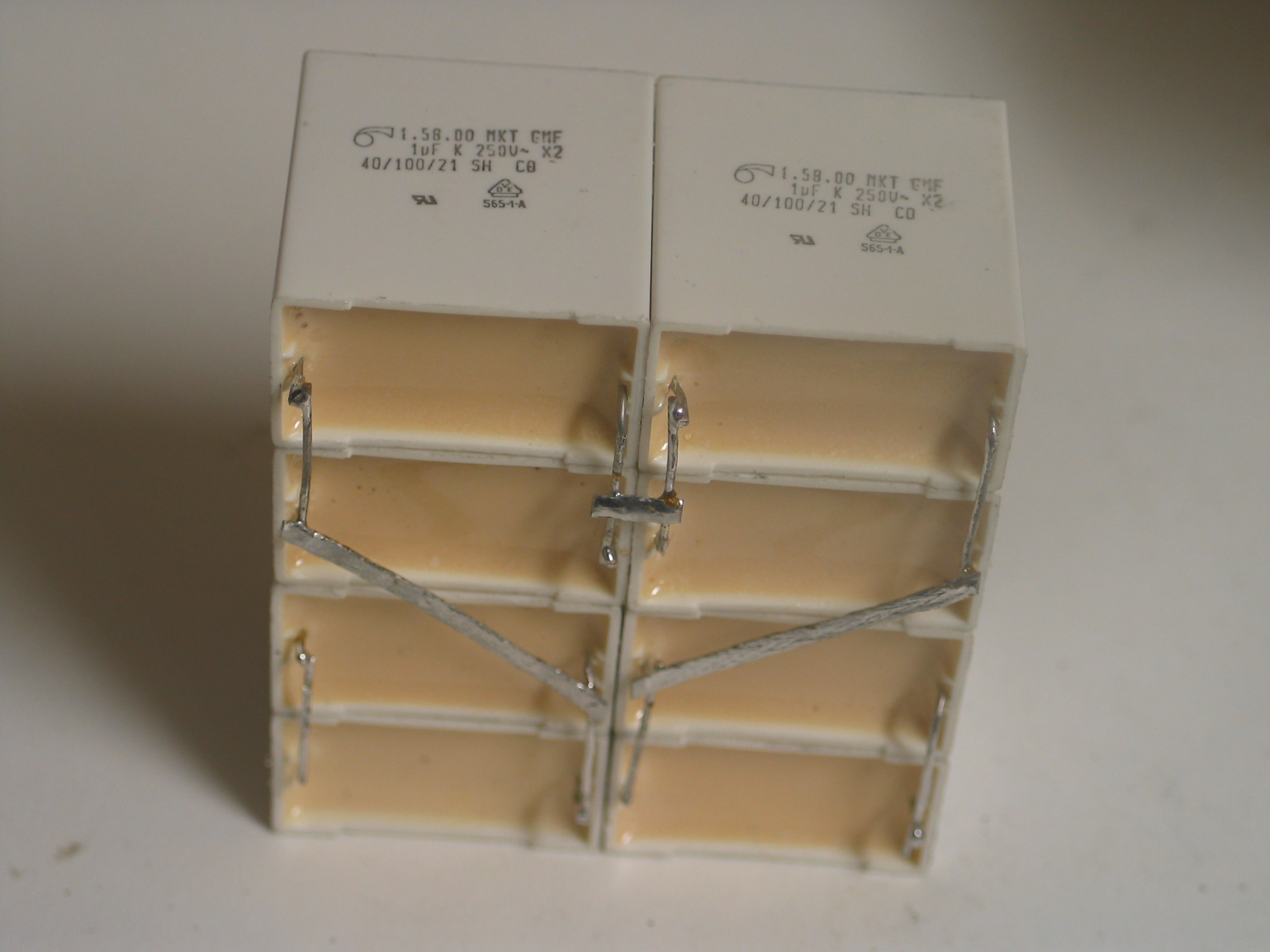
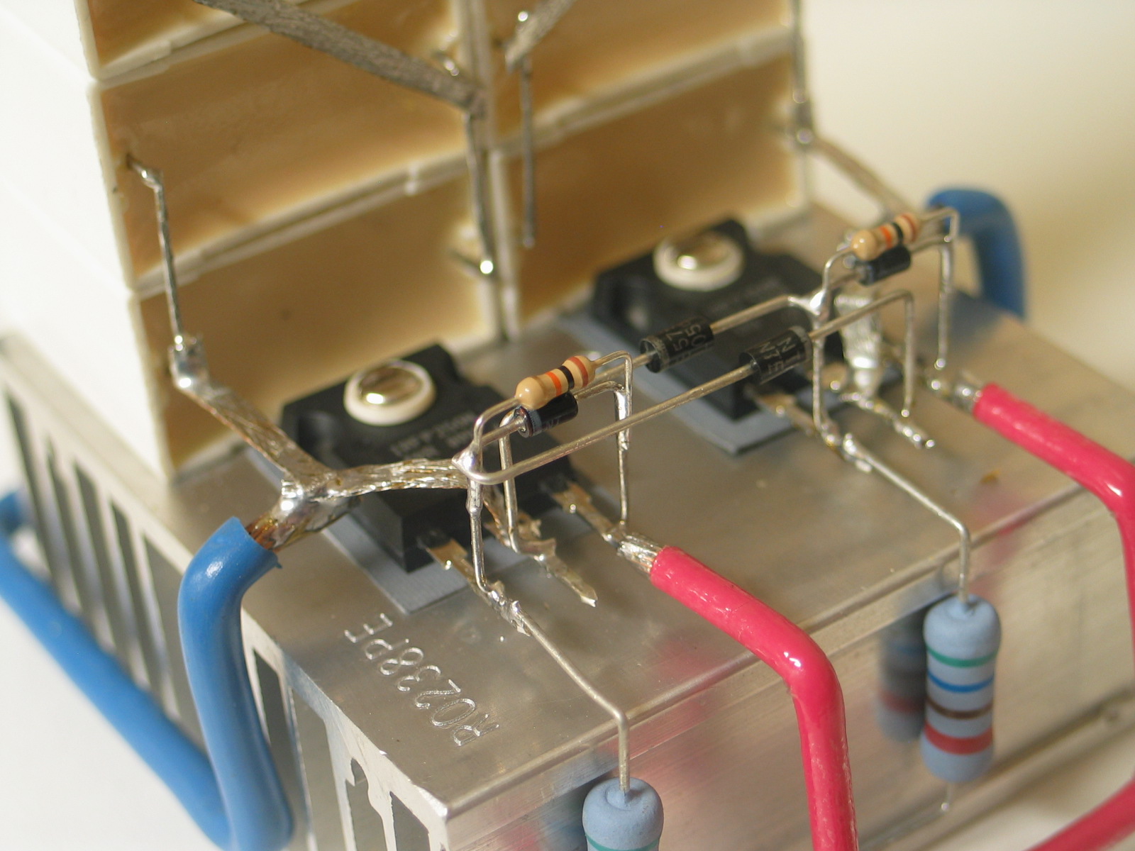
This project sat in my project box for a long time and eventually, I got the motivation to try to build a higher power design. This time, I used the IRF250N that I got cheaply off ebay. One has to be careful about ordering semiconductors from ebay. They arenÆt necessarily the part you ordered. Instead, they might be a repackaged lower power device and would fail in normal use. The devices seemed to handle the high current and voltage well so I think they were legitimate IRF250Ns. In this design, there are even shorter wires and a larger heatsink. The distance between the capacitor and the MOSFETs was minimized because stray inductance in the tank shouldnÆt be too much of a problem. It would just be swamped by the inductance of the primary of the flyback. Also in this design, I built the entire thing around the MOSFETs since it seemed if I built it that way, shorter wires could be used. I added bends at the ends of the diode/resistor modules to make it easier and neater to replace MOSFETs if they were to die. This driver design used separate supplies for the gate and flyback so that higher powers could be produced. If wanted, I could tie the two power supply inputs together and it would have the same supply voltage. Having the option is better than having them always be tied together so I can experiment. The design is quite flexible so there were many changes over time. Some of them are adding more capacitors to the capacitor bank, changing the gate resistors, and adding ferrite beads to the gate lead. The capacitors were changed from two 1ĄF 250V caps in series to eight in a series/parallel arrangement to spread the power dissipation between them. The capacitors would get a little warm otherwise but it wasnÆt much of a concern. As arcs were drawn out with this setup, the arc would squeal before extinguishing which was strange. Changing the tank capacitance to 1ĄF (four caps in a series/parallel arrangement) got rid of the squealing but decreasing the frequency shouldnÆt do that necessarilyģ (8/12/08)
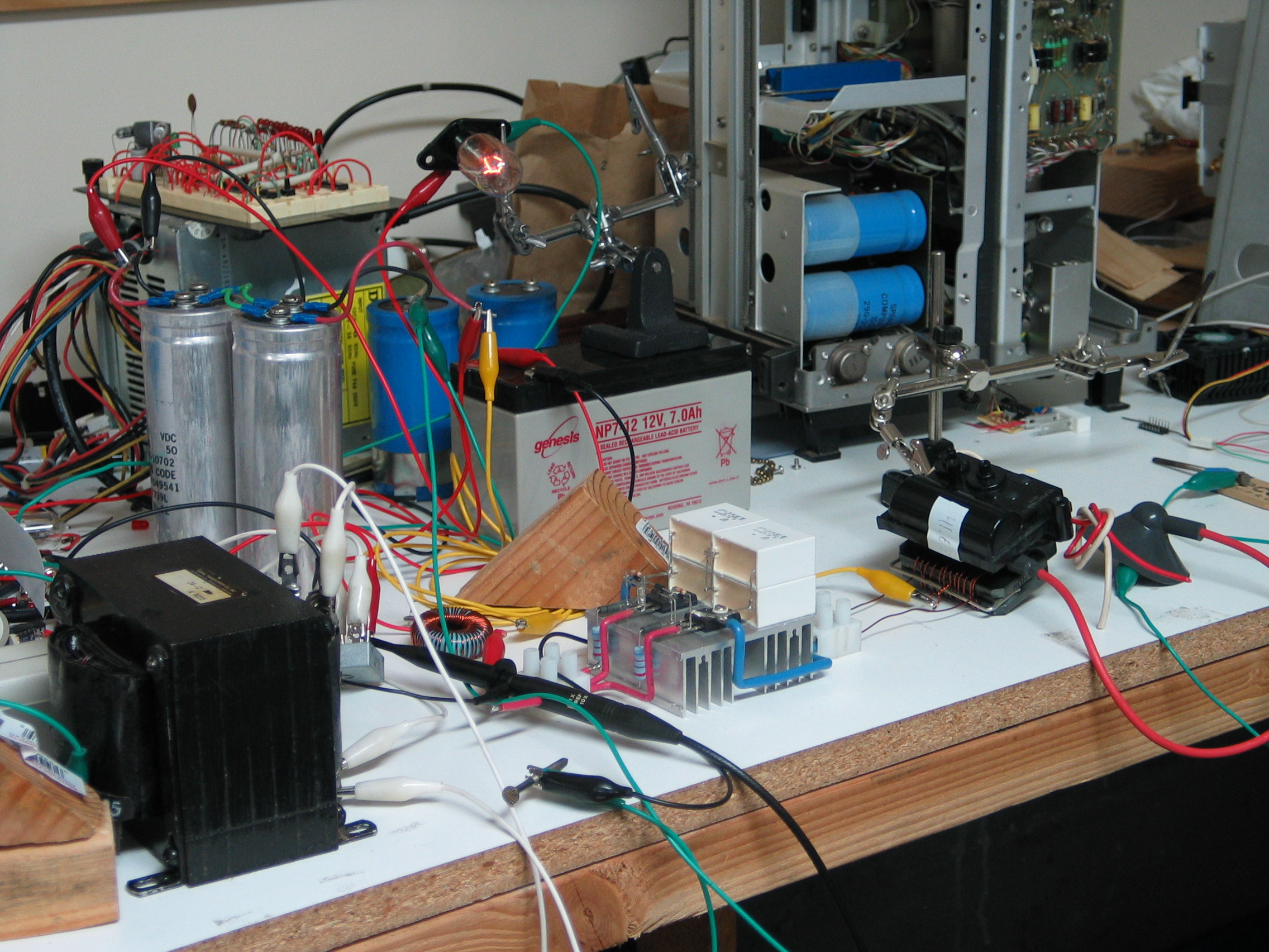
I made a very simple power supply from a transformer from my local electronics swap meet. The voltage would drop quite a bit when drawing arcs but thatÆs probably due to the alligator clips. The alligator clips werenÆt designed to carry this current (about 10A at 36V that drops to something around 30V). To have a visual indicator and also a bleeder resistor, I used a microwave oven lamp. The lamp glows when the power supply is on and also bleeds away the chare from the two large filter capacitors. Bleeders are needed for safety reasons. One doesnÆt want to get shocked or be surprised when the caps are shorted if they are just moving them around. The 12V battery was used for the gate supply.
Conclusion
Overall, I am happy with the performance and hope to someday improve on this design somehow. Many people on the 4HV forum make threads on this driver but none of them are any different in design. It may be a while before I can actually contribute to the design but I hope to do so in the future.
Multiple people on 4HV have used my layout design or something similar because they liked how it looked. [1], [2].