Realization Constraints and Radar specifications
For a radar class I took in 2012, we wanted to focus more on the radar's operation than construction. The goal was to cover doppler radar, range finding, and SAR. We also wanted it to be easily powered and portable so outdoor measurements could be made. This gives us these realization constraints:
From this, we can start defining a SAR system's specifications. The system will be able to operate in the other modes.
2.4GHz is the lower end of an ISM band used for wifi so components for this frequency range would be readily available.
This is a product of the VCO selected and the relatively small operating range (the system's chirp generation is open loop so the system relies on the VCO's tuning linearity) to stay within the op-amp's output capabilities.
There are three commonly used waveforms for SAR: pulse modulation, linear frequency modulation (LFM), and phase coded modulation (PCM). The easiest to implement is LFM due to the lower average power (excluding pulse modulation) and overall system simplicity (excluding PCM).
The reflected signal should be stronger or at least comparable to the signal leakage. We don't want there to be so much leakage that it saturates the LNA in the receive chain or limits the dynamic range in the ADC.
The system should be portable to take the multiple measurements needed to create the SAR image. 12 hours of continuous operation gives a generous operation time in the field to minimize the chance it runs out of power. AA batteries are readily available, rated at roughly 1800mAh allowing us 150mA maximum current draw. At 6V, this comes out to 900mW so aiming for less than 1W of total power consumption is a decent target.
The system should be safe (low EM fields and voltages) and easy (no large components or complex setup) to operate.
Design
...
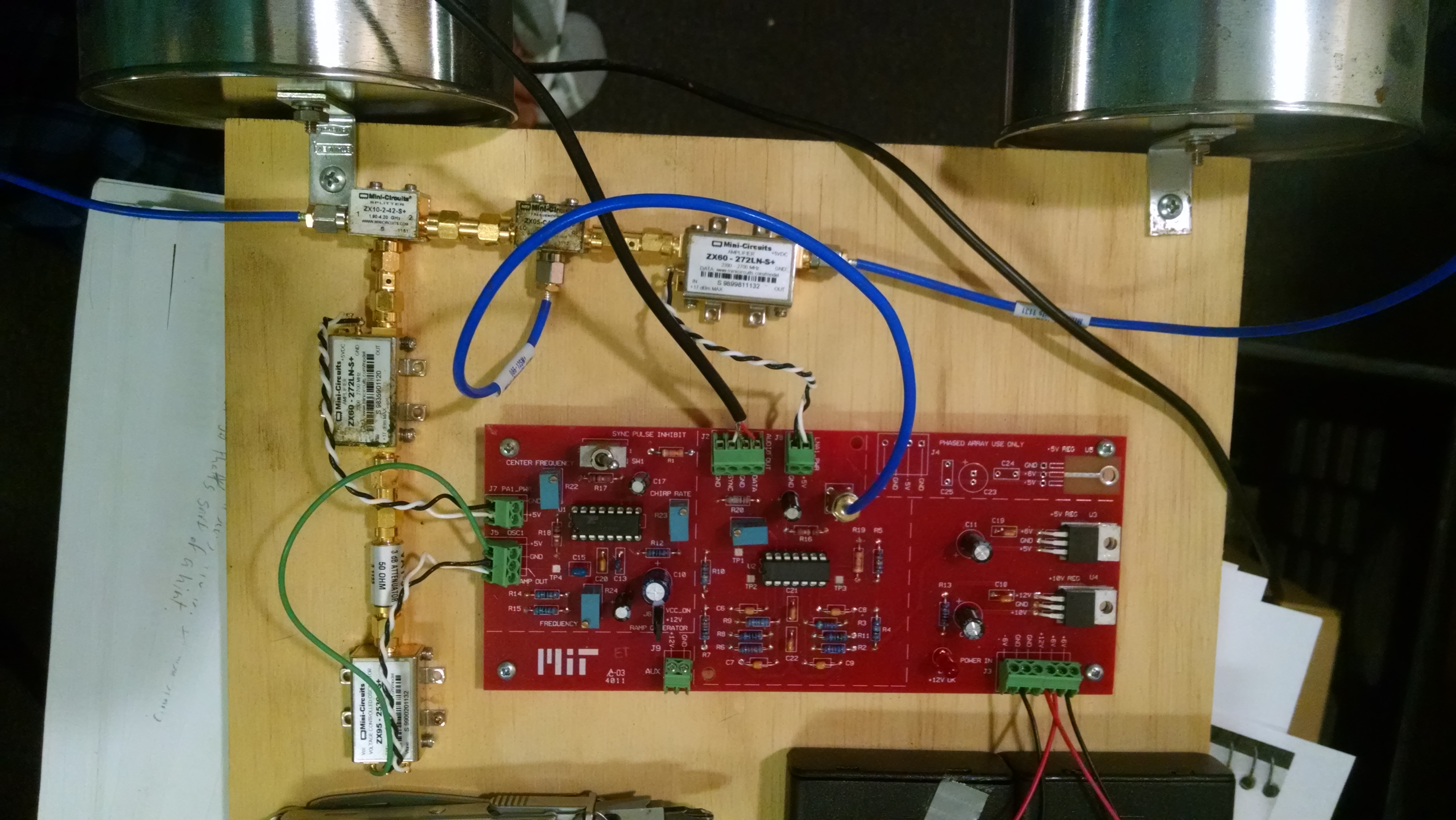
Construction
It was fairly straightforward since the RF portion of system was designed to be modular.
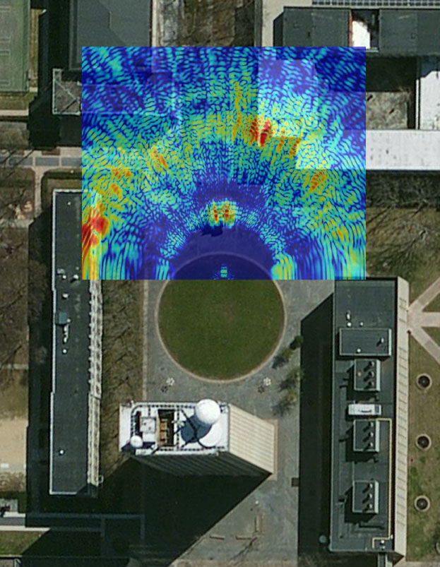
Measurement Results

Processing Methods
Noise Analysis
Conclusion
Intro
...
WR-90 (8.2-12.4GHz) waveguide components seemed the most available and easily configurable for X band experiments. At the time, I didn't have a source for any low loss laminates or software to do EM simulation of stripline elements/filters. Even 2nd hand LNAs and mixer modules for X band operation aren't cheap so creating a full system seemed difficult. Luckily, there are plenty of commercially available LNBs that operate near X band and should be a cheap source of the necessary parts.
Particular Requirements
...
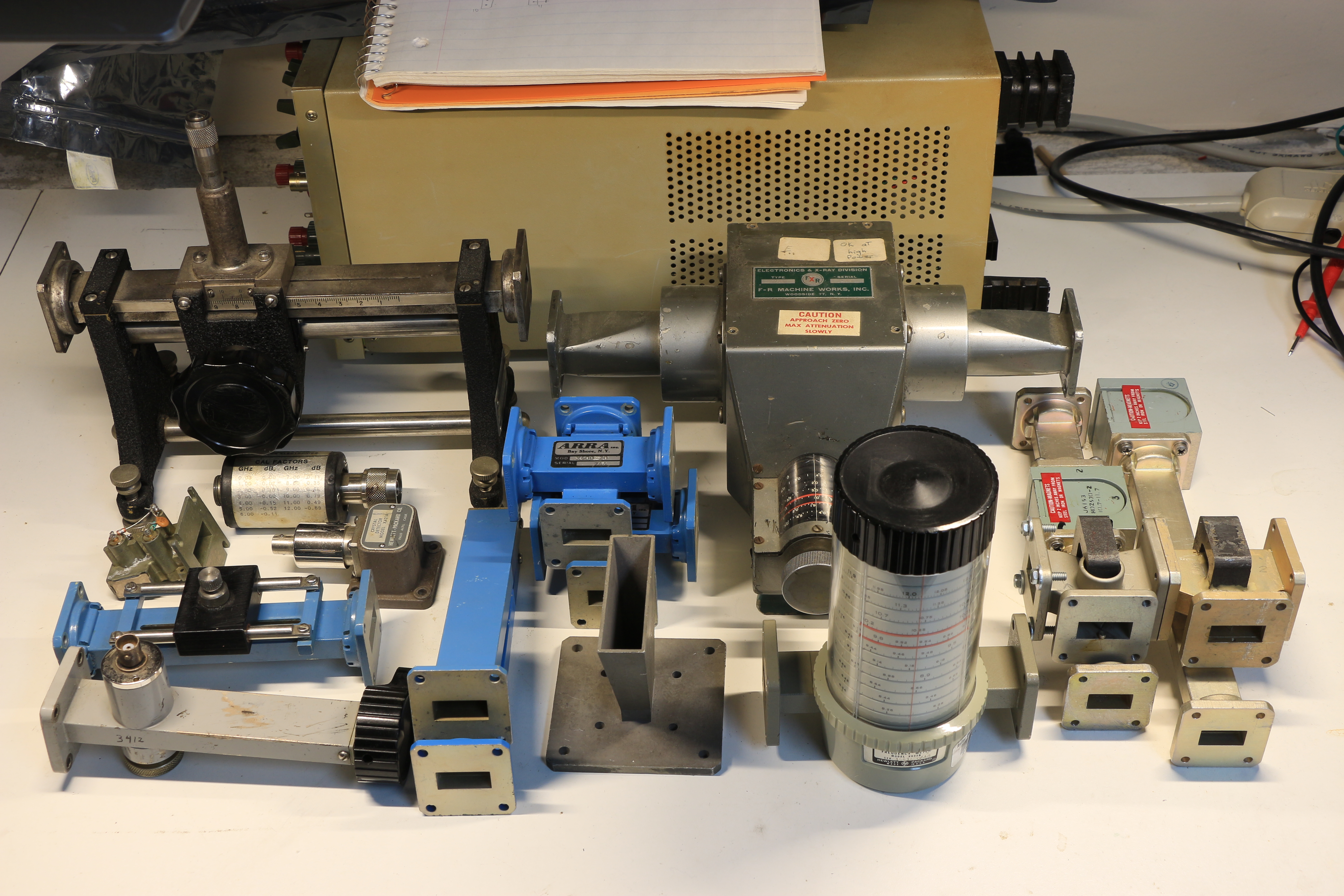
Components
Some waveguide components obtained cheaply from hamfests and Ebay auctions.
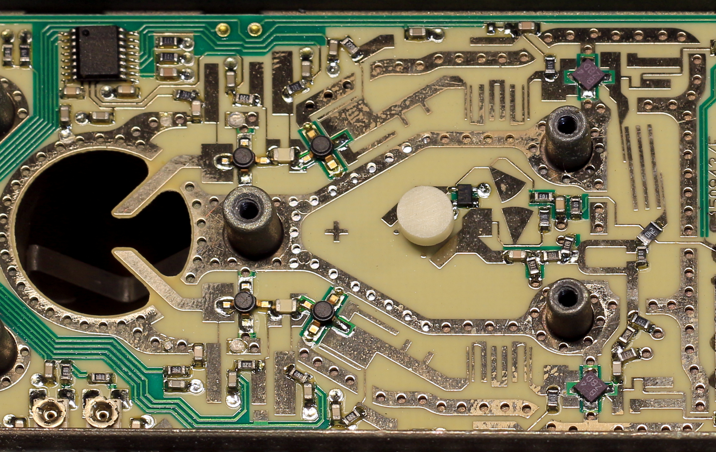
Insides of a simple LNB. On the left is a 2 stage LNA for each channel (different polarizations) and on the right are the mixers. The DRO is in the middle, usually covered by a shield with tuning screw placed above the ceramic disc.
Radar specifications
...
Design
Left in the design stage since the required test equipment isn't available. Some components can be roughly characterized though.
Intro
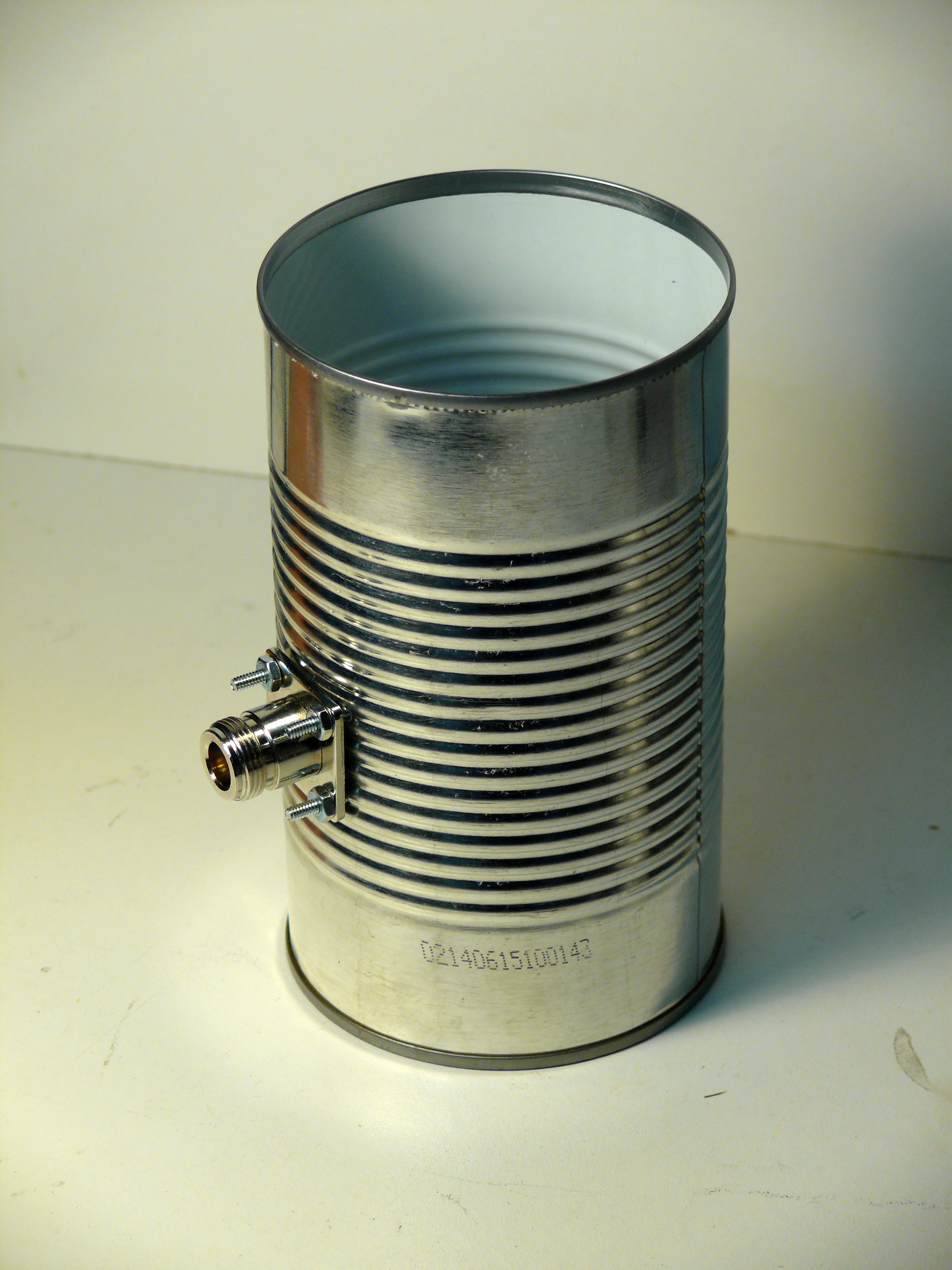
The cantenna is a name given to a circular waveguide made from a metal can. A waveguide is a metal tube that allows standing EM waves to travel down its length with very little losses. They can be used as a directional antenna themselves or as an illuminator for a reflector. Some sites say that a Pringles can works for 2.4GHz operation but since the tube is so narrow it doesn’t work as well as it should.
Where is/was it Used?
Rectangular waveguides were designed before circular ones. The rectangular one was realized first since it makes more sense that it would work but later on, it was found that circular ones also worked for waveguides.
How I Came Across This and why I Built it
My school has an internet filter and it’s rather annoying when I need to look up some magic card and the filter blocks it because its considered games. I knew wifi routers operated at about 2.4GHz and figured if I could direct the antenna enough, I might be able to get the signal to span the distance between the roof of my house and the school. The router’s signal isn’t very strong since it’s not meant to go all that far so it’ll be a challenge to get it to go about ľ of a mile and still be able to communicate. I wouldn’t just be able to stick an amplifier at the output of the router since it also needs to be able to receive the signal from the device, not just talk to it. There were two fairly easy to build, highly directional antennas I found. They were the cantenna and the biquad antenna. Both could be used to illuminate a parabolic dish and achieve higher directionality. The cantenna seemed easier to build so I decided to build this one first.
This biquad design has very high directionality so I may try to use something similar in the future: http://www.qsl.net/yu1aw/ANT_VHF/fid24ghz.pdf
Design and Construction
I didn’t exactly understand the equations mentioned here: circular waveguide modes but will probably understand them more in the future. Till then, I took the easy way out and used a calculator to tell me what can diameter I should use.
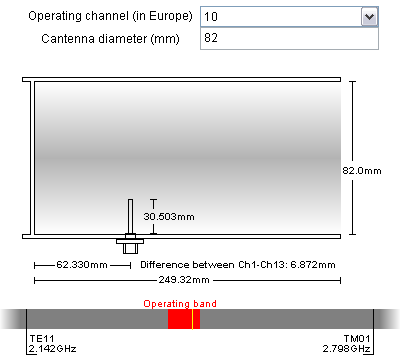
Cantenna Dimentions Calculator
From this calculator, for channel 10, I found that my can diameters could be between about 75mm to 90mm in diameter. I went to a local store and looked for cans that fit this range. There weren’t many but I did find one that had a diameter of about 82mm. The dimensions of the cantenna came from this calculator.
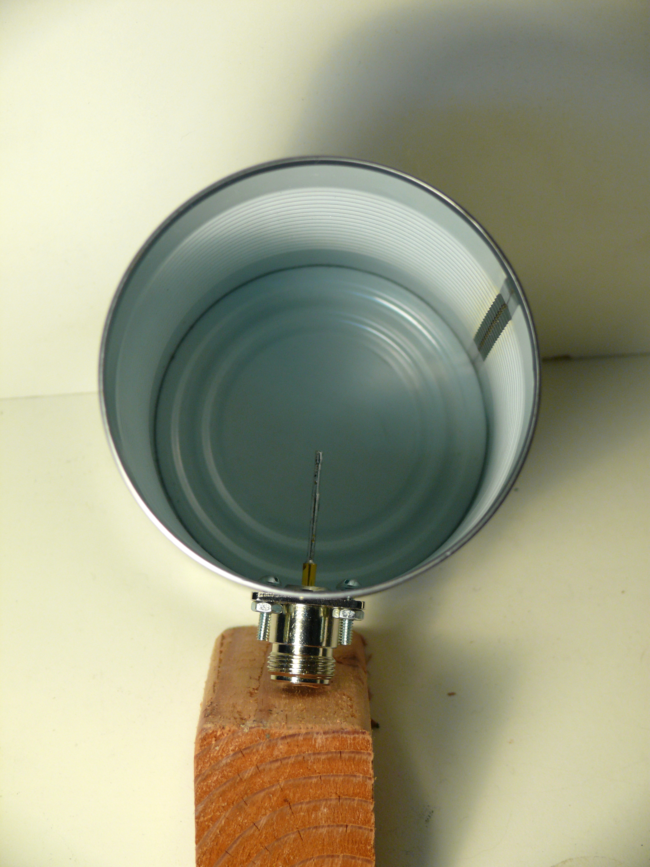
I used N connectors since they are easy to use and have low losses at high frequencies. I got some crimp male connectors and panel mount female connectors to use. One of the pins broke while crimping it onto the central conductor of the mini 8/U cable. I soldered the pin back on trying to keep the heat to a minimum to prevent the insulation from expanding. Sadly, it had expanded so I used pliers to press it down a bit and then pushed the cable in. After I got the conductor and insulation in, it was fine and I slid the crimp rings down and crimped it. The router didn’t have an N connector so I had to use a female N to RP-SMA female. I’m not sure I got the correct terminology right for the RP-SMA but it has threads on the inside and fits onto the router’s antenna connection.
To do a simple test, I connected the omnidirectional antenna to the router and walked up the street, to stay in line of sight, and noted the point where my droid phone said the reception was about -90dbm. Then, I connected the cantenna to the router and aimed it up the street. The phone said the reception was about -70dbm. This is highly inaccurate but it shows that the unfinished antenna is already better than the omnidirectional one.
I didn’t have the proper measurement tools to see how the far field looks so I looked around for simulators and found 4nec2. Their default cantenna looks like this:
And has the code:
CM COFFEE.NEC
CM Coffee can feed - open cylindrical waveguide
CM Horn 300mm long, 176mm diameter
CM by W1GHZ from PA3AEF
CE **********************************************
SP 0 3 .088 -.01394 .300 .088 0.01394 .300
SC 0 3 .088 0.01394 .260 .088 -.01394 .260
SC 0 3 .088 0.01394 .220 .088 -.01394 .220
SC 0 3 .088 0.01394 .180 .088 -.01394 .180
SC 0 3 .088 0.01394 .150 .088 -.01394 .150
SC 0 3 .088 0.01394 .120 .088 -.01394 .120
SC 0 3 .088 0.01394 .080 .088 -.01394 .080
SC 0 3 .088 0.01394 .040 .088 -.01394 .040
SC 0 3 .088 0.01394 .000 .088 -.01394 .000
SC 0 3 .035 0.00554 .000 .035 -.00554 .000
GM 0 4 .000 0.0 18.0
GM 0 0 .000 0.0 9.0
SP 0 0 .015 0.015 .000 90.0 .00000 .0009701
GX 0 110
GW 1 4 .0622 .0622 .100 .0198 .0198 .100 .002
GM 0 0 0.0 0.0 45.0 0 0 -0.300
GM 0 0 0.0 90.0 0.0 0 0 0
GE
FR 0 1 0 0 1296.0
EX 0 1 1 0 1.0 0
LD 5 0 0 0 3.72E+07
RP 0 73 73 1001 -90. 90. 5.0 5.0 10000.0
EN
I had tried making my own with a wire cylinder but it ran into problems when I tried to simulate it. I’ll model my design after this cantenna since it works. I haven’t got around to doing so though.
Future
I hope I can find the time to build this antenna before the end of the year so I can actually use it to access my internet from school. I’ll also want to try the biquad design since it looks quite directional. For weatherproofing, I hope to use Tupperware containers and something to prevent water from getting into the can which would cause it to rust and would affect the performance of the antenna.
Intro
...
Where is/was it Used?
...
How I Came Across This and why I Built it
Datasheets:
MRF571
SAM-5
MHW592
Design and Construction
...
Conclusion
...
Intro
These TTL oscillator cans come in a variety of frequencies from about 32kHz up to 100MHz. The can oscillators aren't as accurate as the discrete crystals but are a lot easier to use in a circuit. All the cans need is a 5V supply unlike the crystals which would need to be part of an oscillator. Like most TTL devices, these cans have a fan out of 10 meaning it can feed the inputs of 10 TTL devices.
How I Came Across This and why I Built it
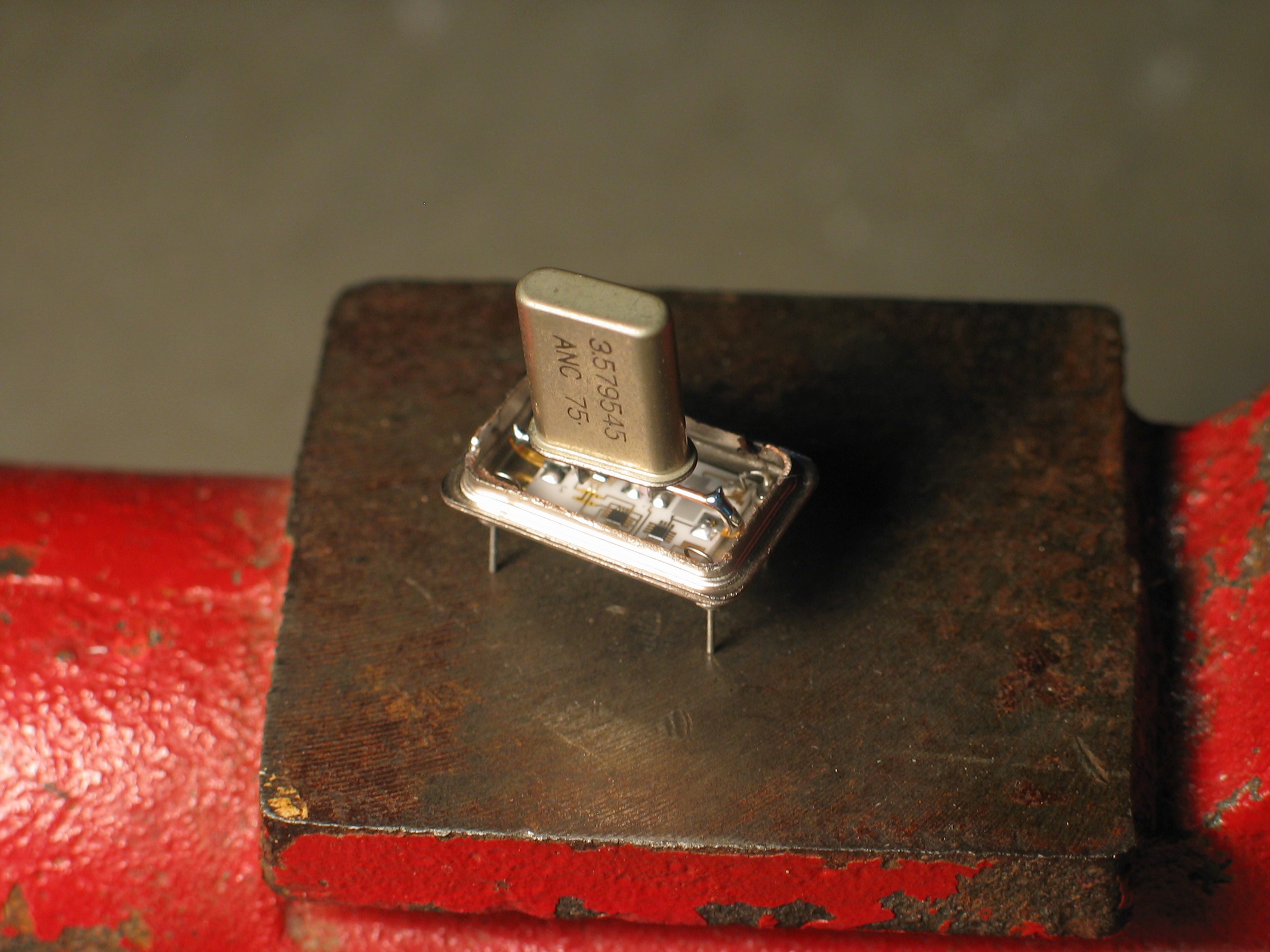
I have many crystal oscillator cans from my electronics surprise boxes. I have duplicate oscillator frequencies so I picked one and decided to cut it open to see what was in it and how it worked. I was expecting to see a piece of quartz and a die but saw this:
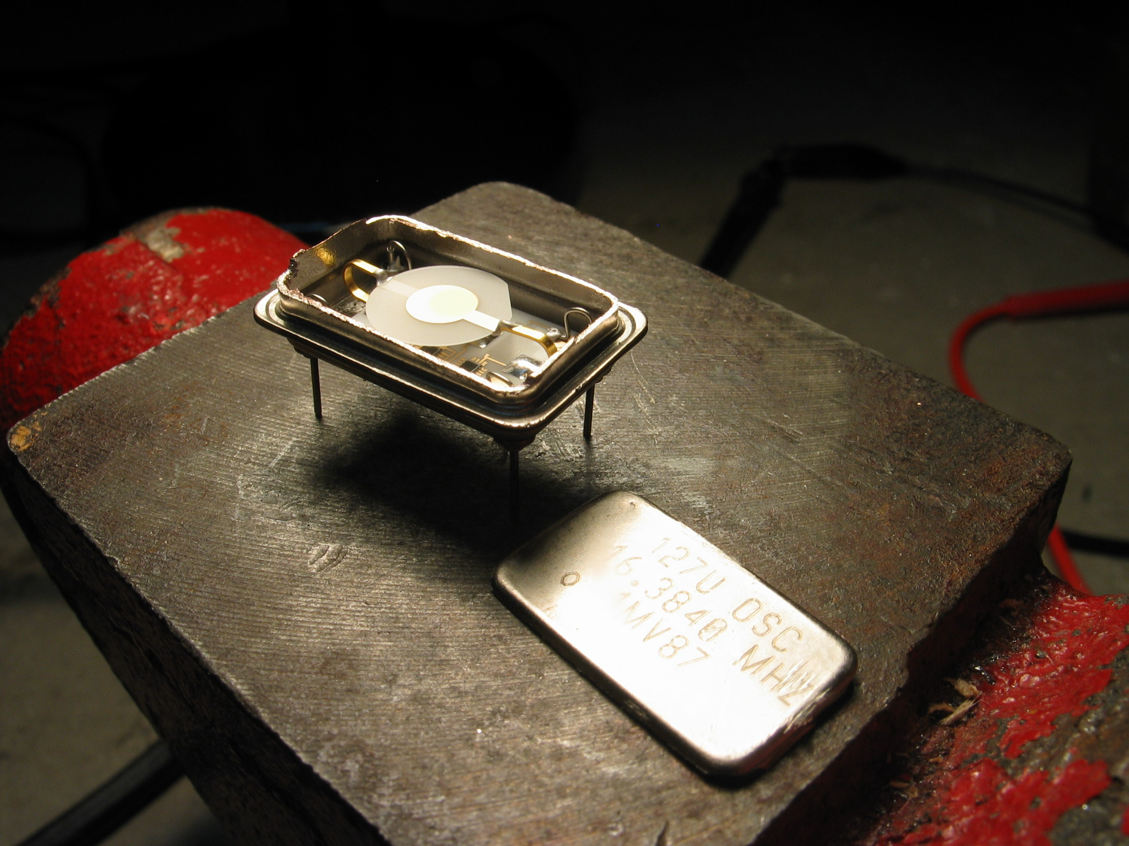
Since the crystal looked similar to the ones in the discrete devices, I figured I could swap them out and see if it would still work.
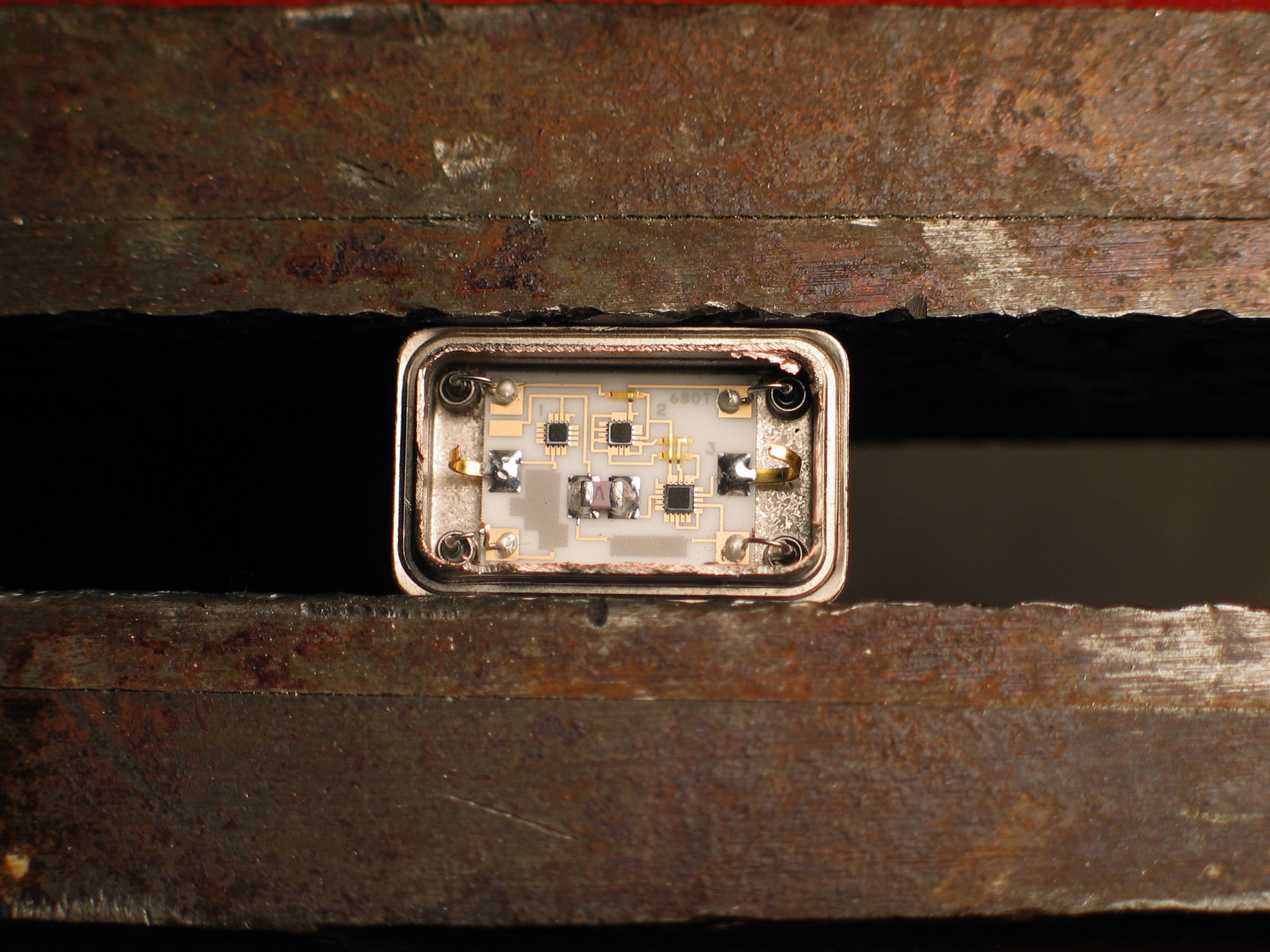
I accidently cut the wire that goes to pin 1 with the dremel when trying to remove the 16.3840MHz crystal. I wasn't careful enough and broke off one of the leads to the crystal.
Conclusion
Well it works! I guess I could use these to make crystals oscillate if I’m feeling lazy. Sadly, removing the existing crystal is likely to break something since it’s so fragile. It may be more work than its worth though.
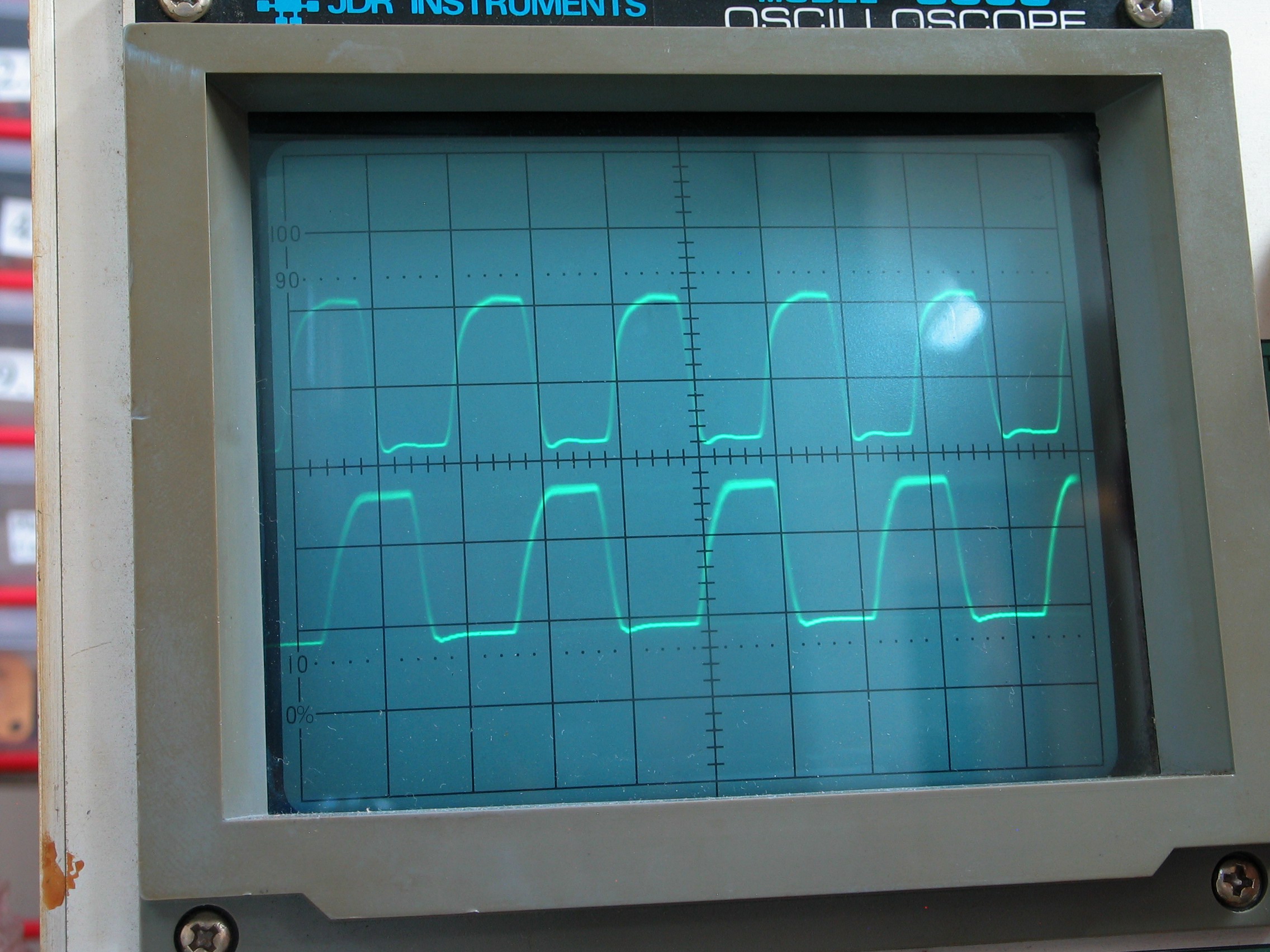
The top trace is a 4.0960MHz unmodified oscillator output and the bottom trace is the output of the modified oscillator (~3.60MHz assuming the reference oscillator is accurate).